AR Build for Rookies Part 3: Upper & Gas Block Assembly
December 16, 2021
T.A. Harrison
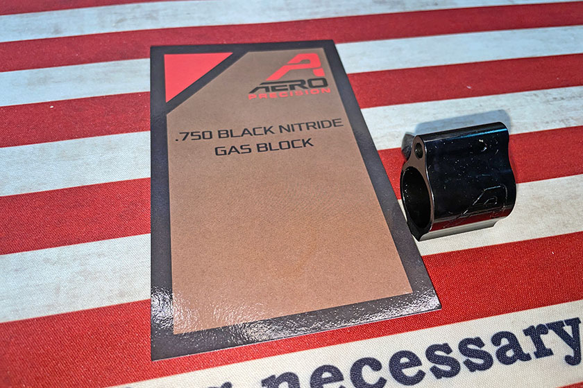
This is Part 3 in a series about building an Aero Precision AR10 kit. If you’ve not seen them, revisit Part 1and Part 2 to get a feel for the process. In Part 3 I’ll illustrate how to assemble the Gas Block and Gas Tube that aids in the round-cycling process, and we’ll also look at installing the Bold Carrier Group and Charging Handle into the Upper Receiver.
I’ll be honest before we dig in, I made a few mistakes in this portion of the project. A couple mistakes that would have been avoidable if I had the correct tools, or if I would have chosen a different path to assembly. I’m happy to show where I messed up so you can avoid the same mistakes.
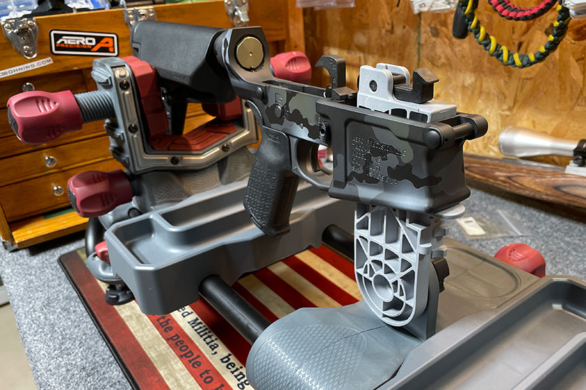
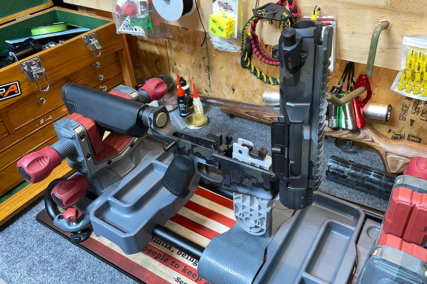
Here is the assembled AR10 to this point. I picked up a Tipton Ultra Gun Vise and I loved having it included in the process. It makes holding the partially assembled rifle in an easy-to-work-on position that doesn’t require any hands. I’d recommend it.
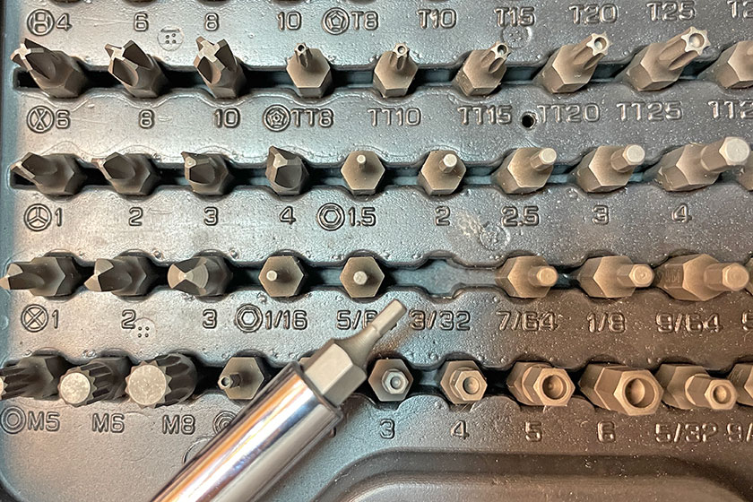
Here’s that Masterforce Drive Bit Set I picked up from Menards I mentioned in Part 2. It came in real handy again for this portion of the project. For the set screws on the Gas Block, I needed the 3/32 allen head.
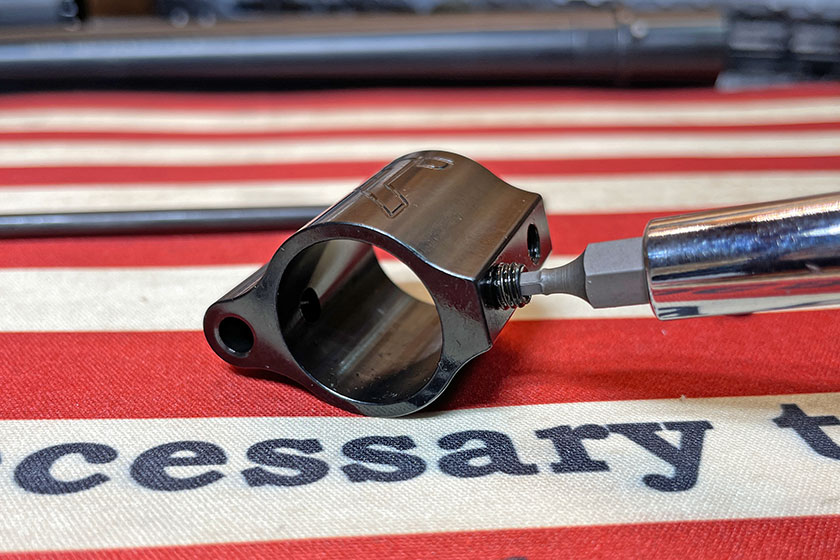
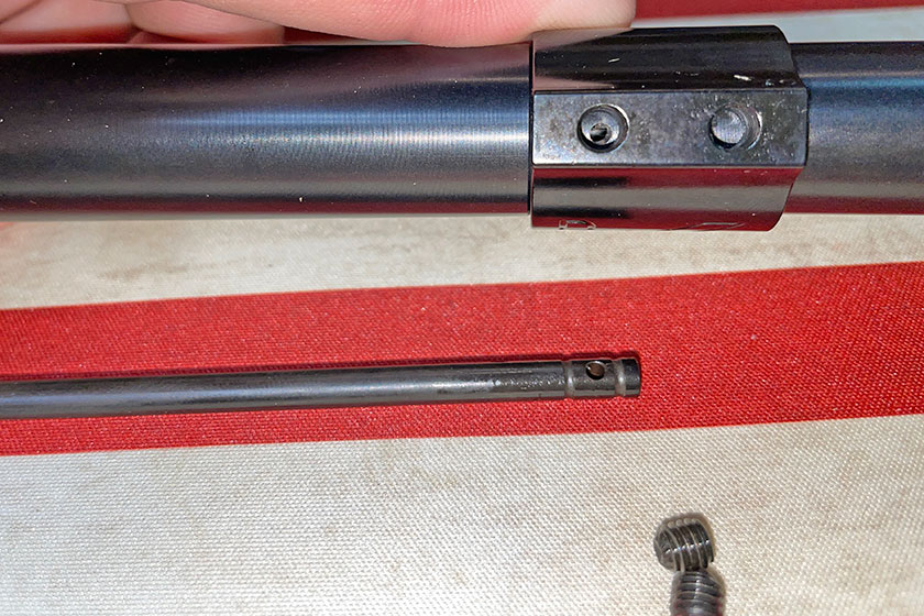
This image shows where the screws are on the bottom of the Gas Block.
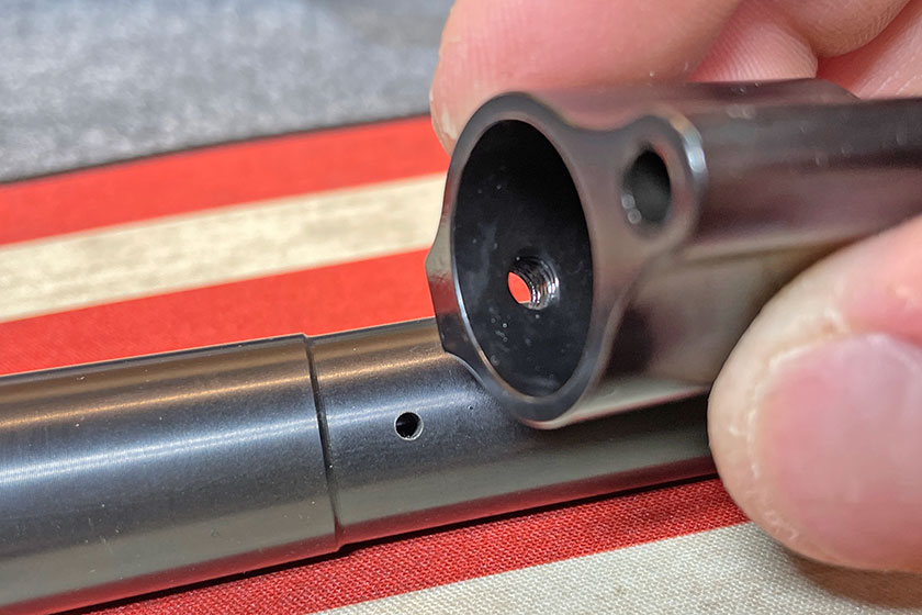
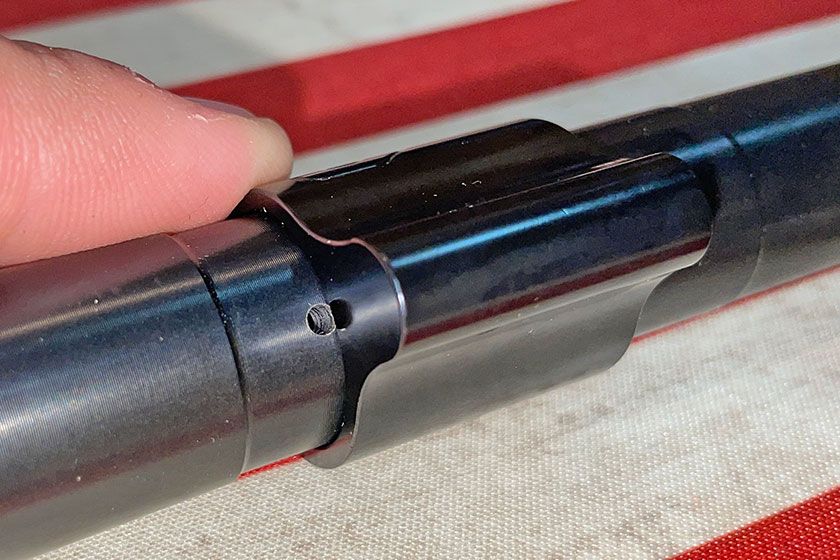
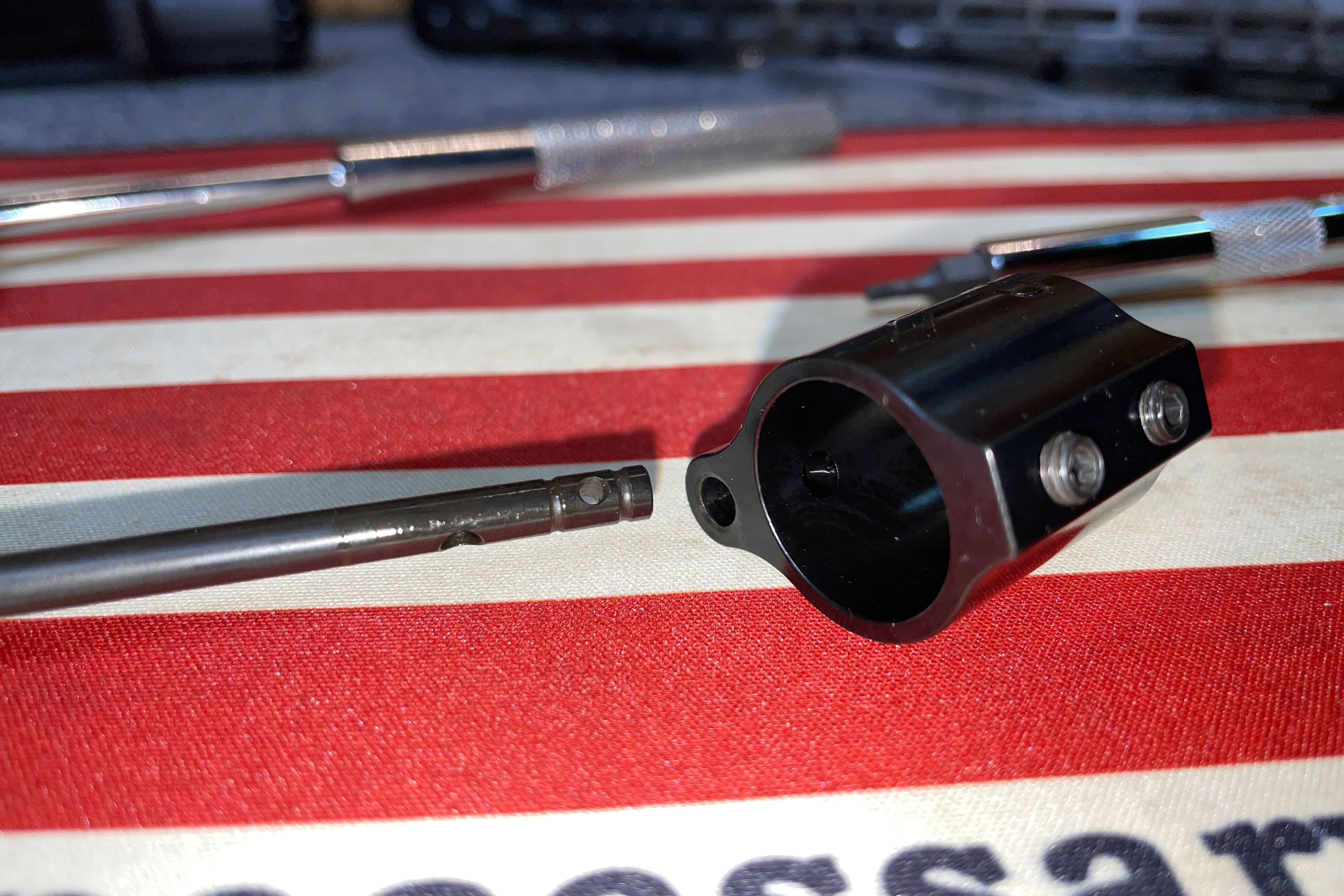
This is essentially the position the Gas Block will take once it’s on the barrel. The hole in the barrel is where gas will be expelled and will match up to where the tube is inserted in the Gas Block. It helped me to visualize this step to look at them this way.
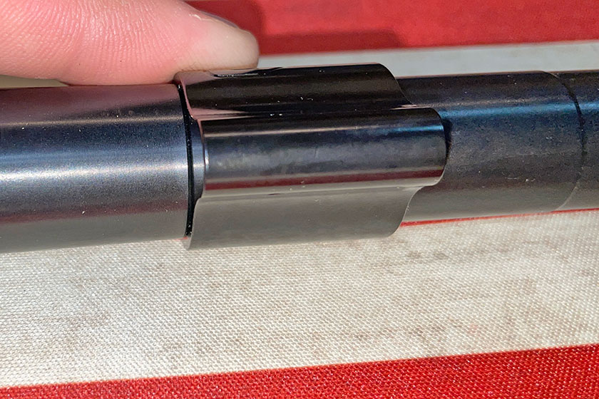
This image illustrates how it will fit on the barrel. When the Gas Block is moved back on the barrel to bump against that ridge, the hole in the barrel will line up with the Gas Tube port inside the Gas Block. This video was helpful in me getting through this portion of the project. Watch the video and remember the hockey puck.
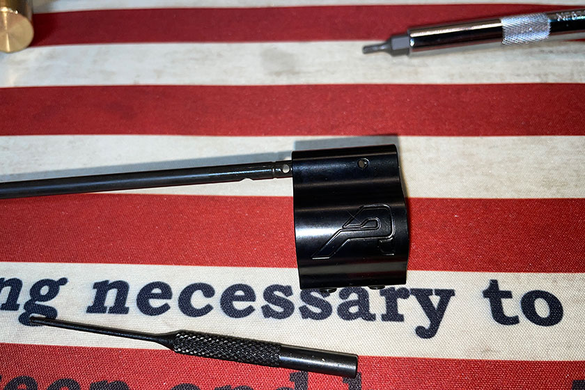
Here is the Gas Block in position.
If you spin it 180 degrees, you can see through the set-screw hole and into the hole where gas will be expelled from the barrel. This helped me visualize how to position it when it comes time to crank it down.
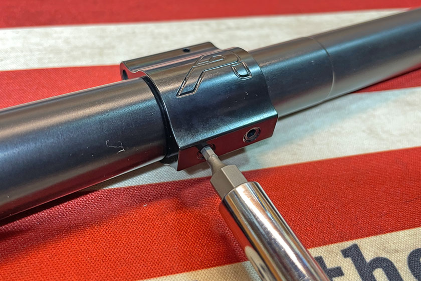
Once I had it lined up as perfectly as possible, I cranked the set screws down firmly knowing it would mark the barrel.
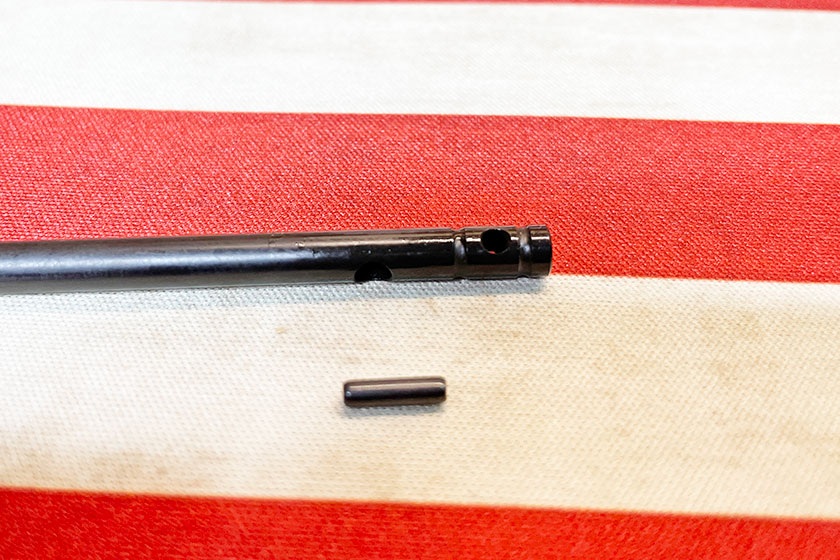
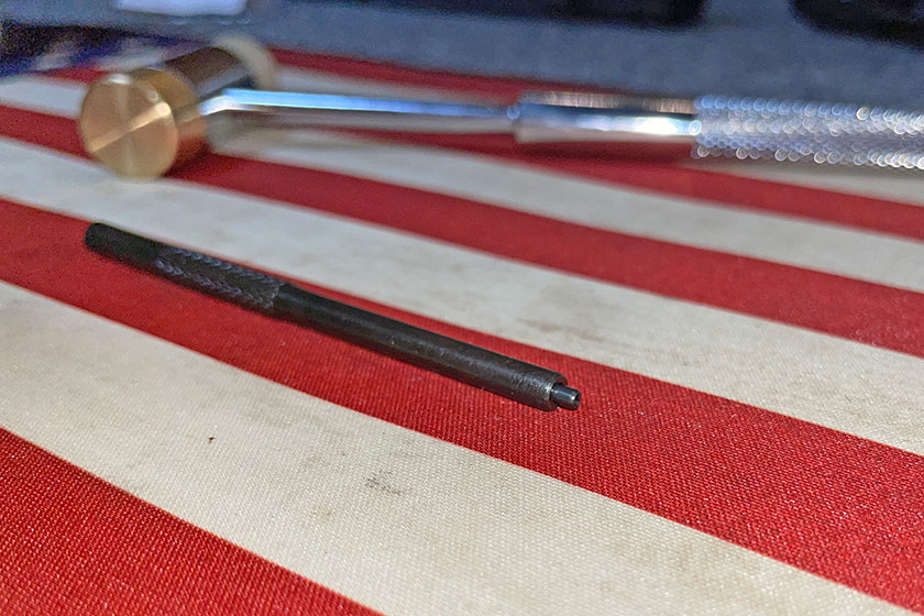
Here’s a shot of the end of the Gas Tube as it will fit into the Gas Block and a roll pin to attach the tube to the block.
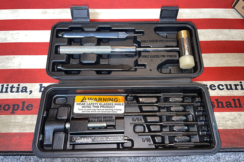
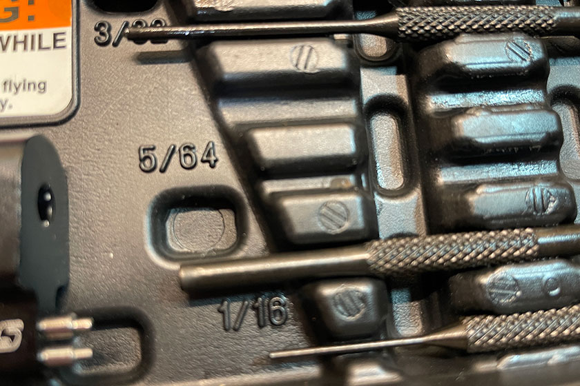
The two punches associated with the 5/64 are meant for placing the roll pin through the Gas Block and Gas Tube.
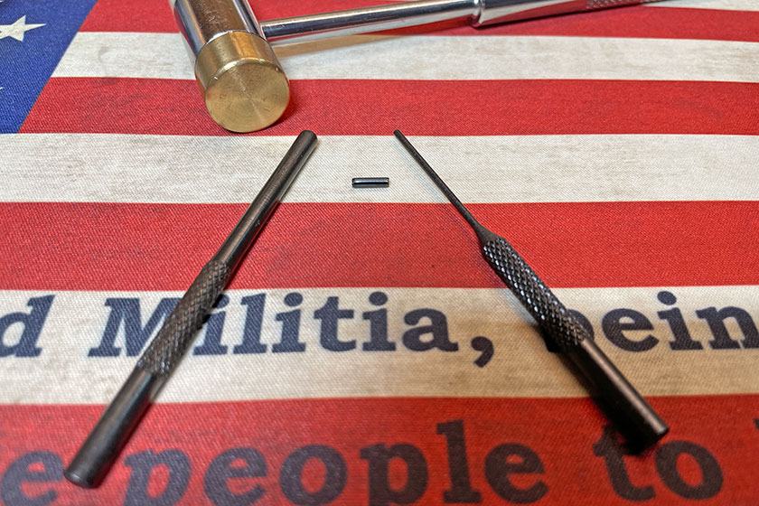
Here are the two punches and the roll pin.
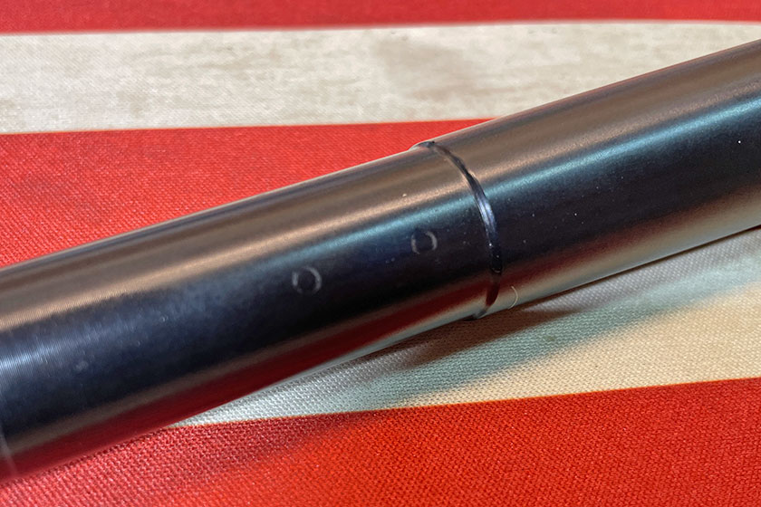
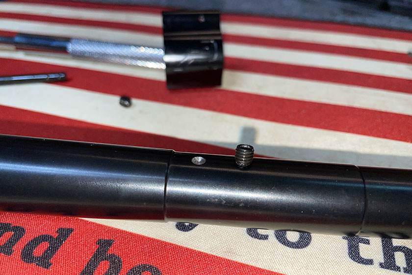
In this photo you can see the marks I made by cranking down the Gas Block set screws.
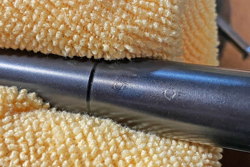
Here is another shot of the same marks. In this image I’ve moved to my tool shop and placed the barrel in a vise to dimple the barrel for the set screws. This is one of those points in this project where I think I screwed up. I watched this informative video about dimpling the barrel, and I think this guy nailed it. However, after quite a while researching the topic, I found mixed opinions. Of course, manufacturers don’t necessarily recommend dimpling the barrel to give each set screw more “bite,” but there is value to the process. Based on all I’ve read on the topic, I think it’s a worthwhile effort if you have adequate tools, experience and confidence to perfectly perform the job. Otherwise, I wouldn’t recommend doing it. Perhaps call a gunsmith, but that is a counterproductive decision if you’re building this on your own. To get it right, an experienced technician might be the best bet. The Aero Precision kit and this barrel features the rib where the Gas Block stops. In the following steps you’ll see I chose to dimple the barrel, and frankly, I did a crap job at it.
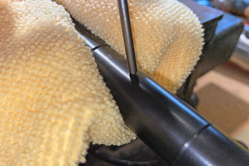
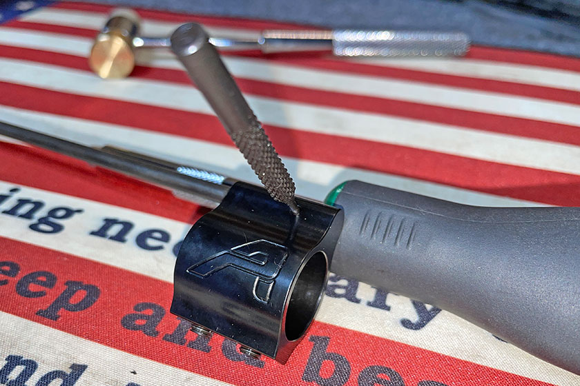
I used a punch to mark the barrel to provide the drill bits a place to bite in and start the dimple.
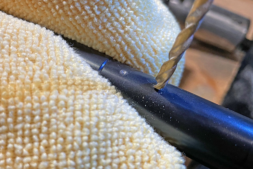
I started each dimple with a 1/8-inch drill bit and followed up with a 5/32-inch bit.
It was difficult to get the punch exactly centered, and with each upgrade in size of the bits, the holes seemed to become more off center—albeit a tiny amount.
I didn’t measure the depth of each dimple, but I kept a set screw handy to make sure it was as little as possible, but just enough. I didn’t take a very scientific approach, and if I were to do it over, I’d be more detailed at this part.
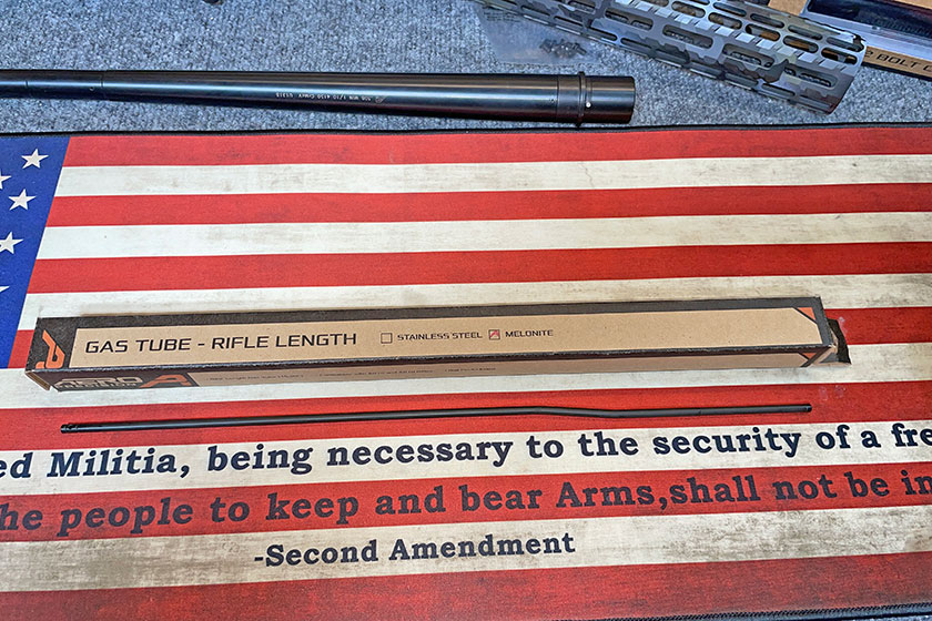
Back to the Gas Tube and Gas Block assembly, I oiled up the end of the tube so it would slide into position without as much friction—just simple gun oil. The hole on the bottom of the tube that’s back from the tip by about an inch is to line up with the hole on the inside of the Gas Block.
It slides in just like this.
Once I got it into position, I used the male version of the two 5/64 punches to line everything up.
Here is the roll pin inside the female version of the 5/64 punch. This is meant to hold the roll pin in place while you tap it into the housing.
I found it was easier to get thing started with the Gas Tube removed.
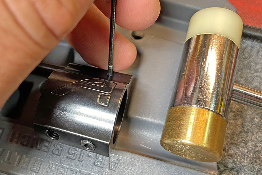
Once the roll pin was started, I lined up the holes in the Gas Tube and finished driving the pin through the Gas Block and Gas Tube.
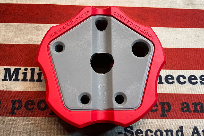
Recall the video that had a modified hockey puck in the mix? Well, this is a product I found after I completed this project. This is the Real Avid Smart Bench Block that would have saved me a lot of cuss words—it’s a non-slip, magnetic universal pin punch block. I’ll be honest once again, assembling the Gas Block and Gas Tube—or just driving the roll pin through—was the most difficult part of the build thus far. This simple $15 tool would have been extremely helpful.
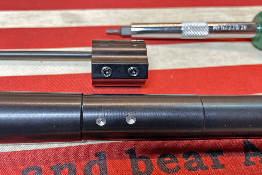
This is the picture I wasn’t looking forward to sharing. You can see how the dimples are out of alignment, but lucky enough for me, they ended up close enough to not affect the rifle’s performance. Bad craftsmanship. But lesson learned.
Here is the assembled Gas Block and Gas Tube affixed to the barrel.
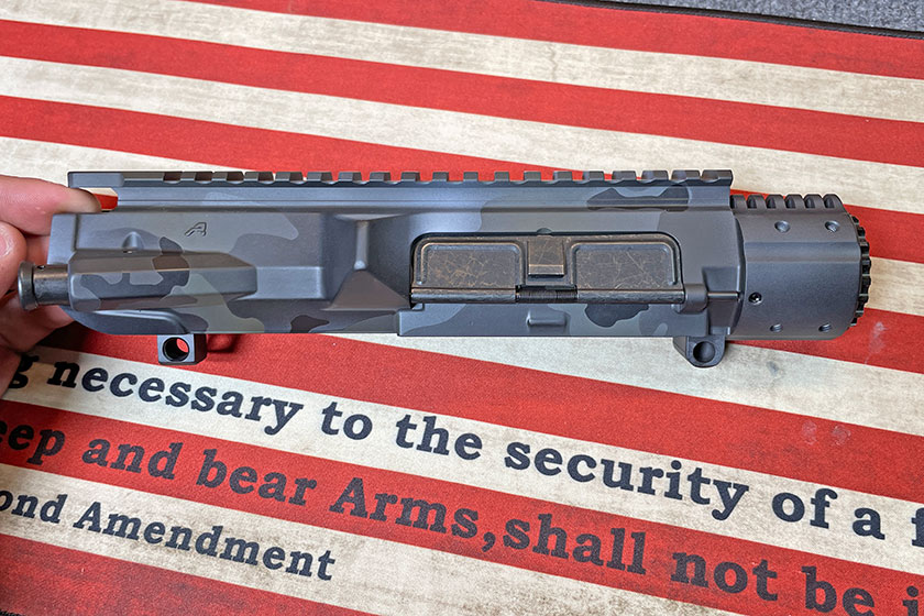
The next step is assembling the Upper Receiver. Man, this thing is sharp!
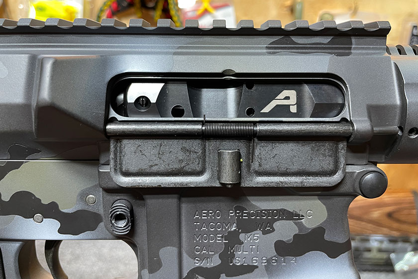
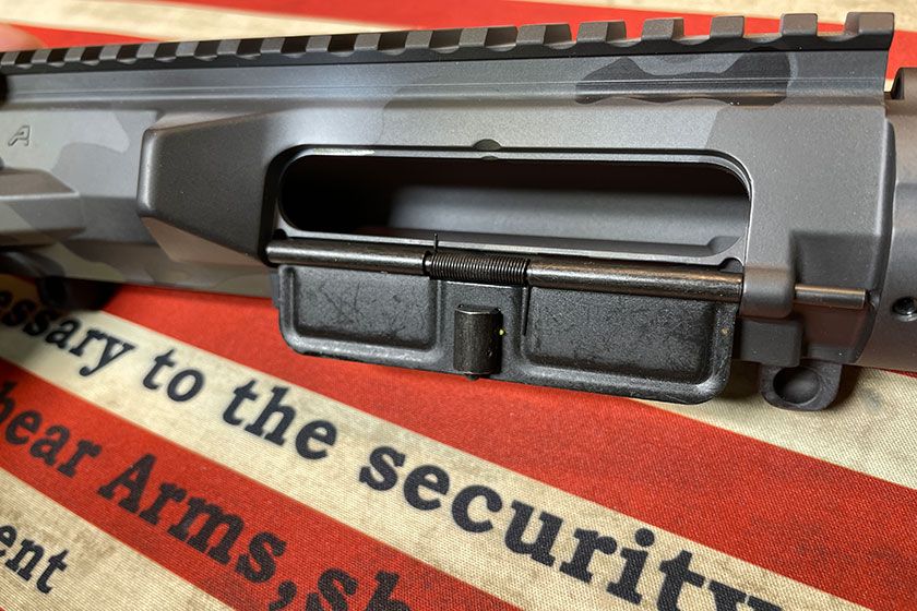
The Upper Receiver came mostly assembled, including the Ejection Port Cover and assembly…
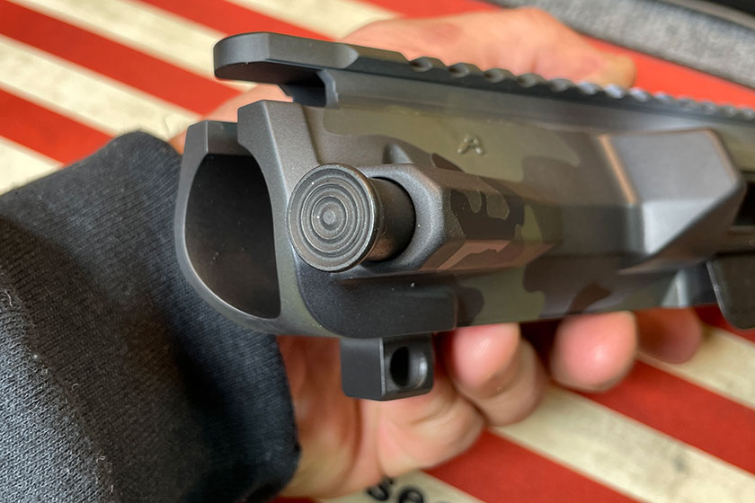
And the Forward Assist Plunger. I kinda wish this kit offered the experience to put these parts together and install them on the Upper Receiver. But it did save me some extra steps in the overall process.
Here is where the Upper Receiver attaches to the Lower Receiver.
Everything lines up perfectly, but it’s not ready to be permanently affixed just yet.
Again, this Tipton vise made my life easy.
This next step requires no assembly, and it’s quite satisfying.
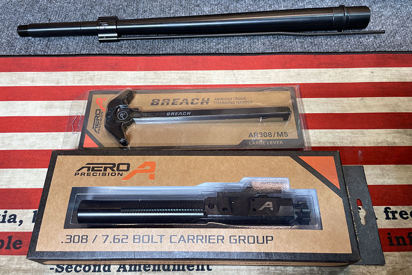
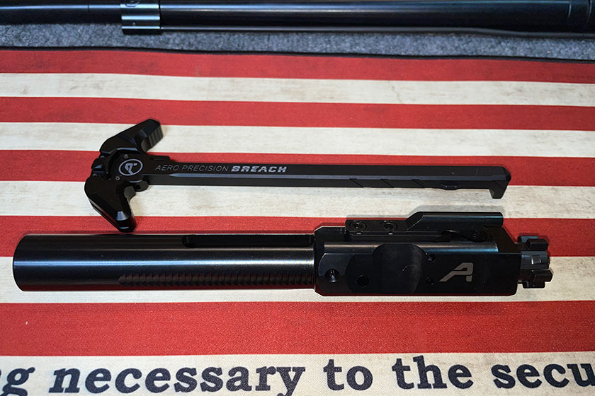
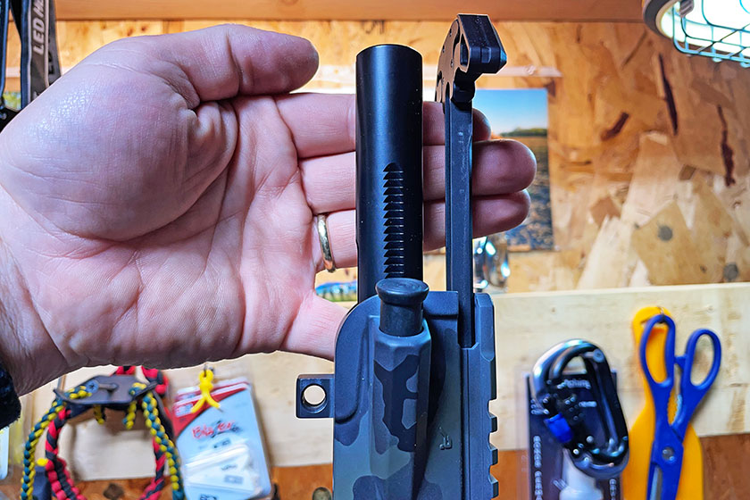
Here is the Breach Charging Handle and the Bolt Carrier Group.
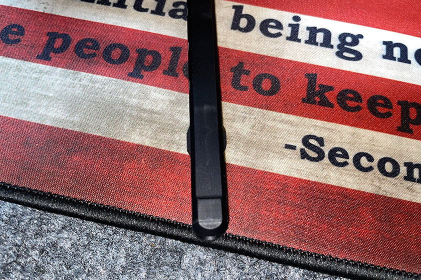
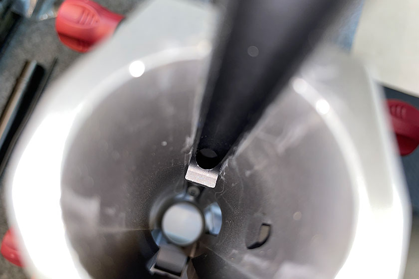
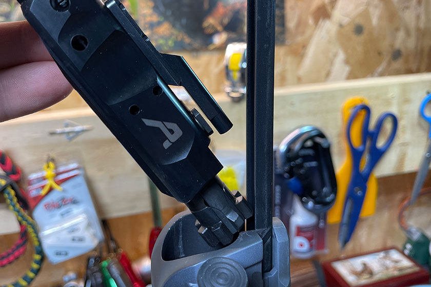
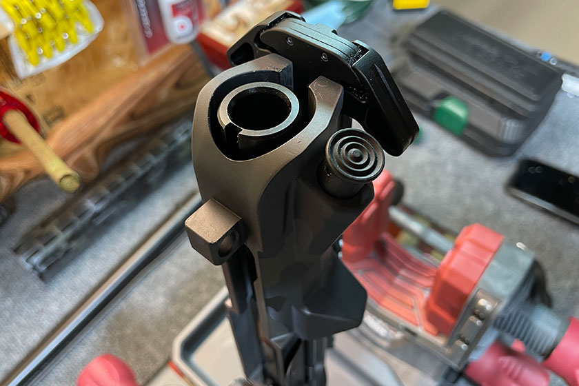
Now looking down the rear of the Upper Receiver, you’ll notice the slot where the charging handle gets inserted.
Near the front end of the charging handle there are two flanges on either side.
The charging handle slides into the matching slots inside the Upper Receiver. It’s a pretty self-explanatory step.
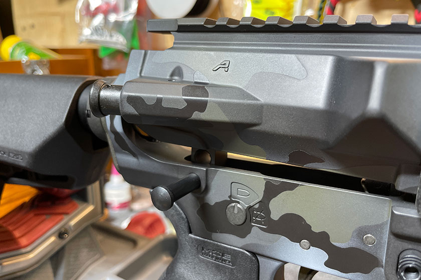
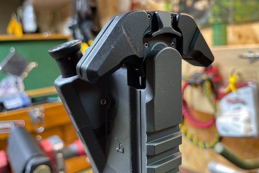
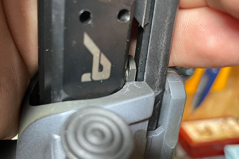
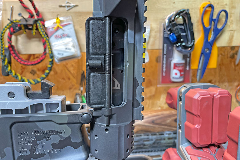
Here is an outside view of the inserted charging handle, but not latched.
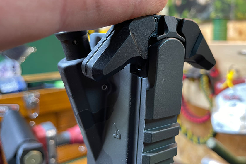
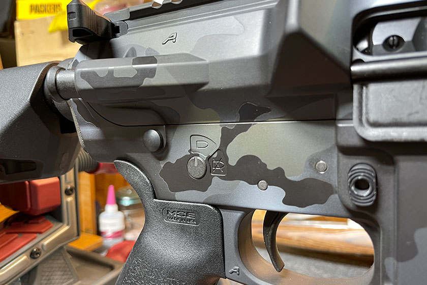
Now it’s fully latched down.
Both latches on either side make it ambidextrous. Lift either one and it’ll slide out. Simple.
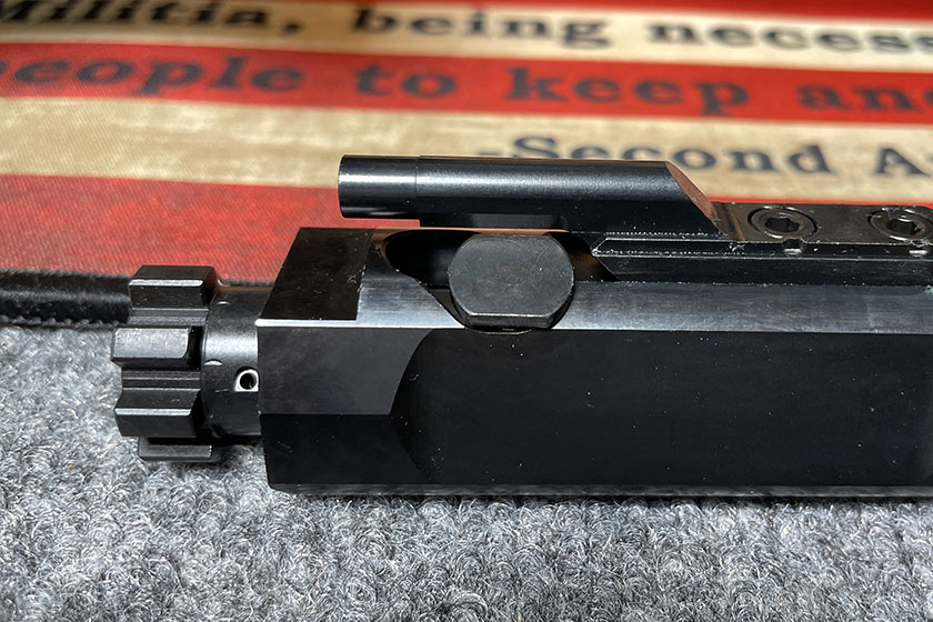
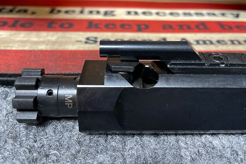
When looking at the bolt carrier group, the oval-shaped button-looking thing called the Cam Pin is out of position for the bolt carrier group to be installed. Simply slide it forward before placing it in the Upper Receiver.
This picture indicates the position the Cam Pin needs to be in for the whole component to fit inside the base of the charging handle so both pieces can be placed into the Upper Receiver.
That tube thingy on top of the bold carrier group is called the Bolt Carrier Key, and it fits inside the underside of the charging handle.
It just slides right in. Super easy.
Once it’s in position, the two components will slide right inside the Upper Receiver.
The bolt carrier group and charging handle are in place and ready.
Here’s another look at the bolt carrier group in place.
And now the Upper Receiver is locked into place and secured to the Lower Receiver.
Done. Next up, we’ll go through the barrel alignment and installation, including the muzzle break. Part 4 incoming. ~ Tom H
Tom Harrison is lifelong Midwesterner and a 25-year veteran angler, whitetail and turkey hunter. His experience extends from the bass rich waters of Mexico well into northern Canada, he's successfully hunted turkeys in 13 states, whitetails in five states and one Canadian province. Harrison has been producing instructional content, speaking at tradeshows and outdoor talk radio/podcasts and creating videos for two decades regarding both the hunting and fishing in an undying effort to help others be the best they can be in the outdoors. His overall goal is to make success commonplace on the water or in the woods through hard work and a strong desire to learn.
Recent Articles
Gun Talk Media Launches New TV Network
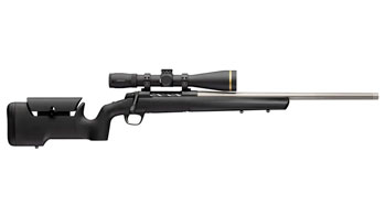
One Rifle for Every Hunt: The Browning X-Bolt 2 Special Max LR SPR Is the Do-It-All Bolt Gun 2026 Needed
S&W Just Dropped the Most Thoughtful Lever-Action Commemorative of 2026. Two Origin Stories. One Beautiful Rifle.